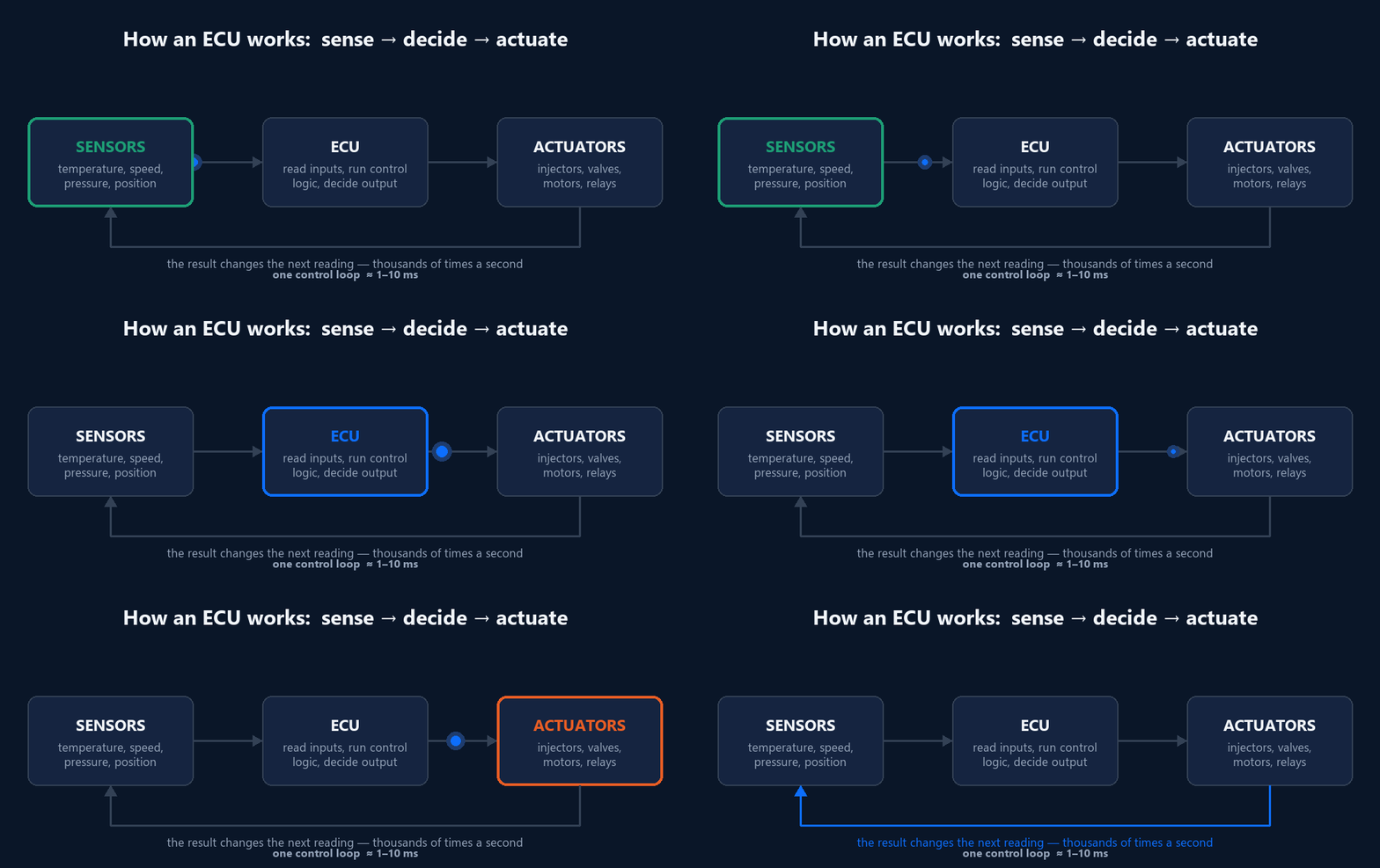
A modern car contains somewhere between 30 and 150 of them, and most drivers have never heard the word. An automotive ECU — Electronic Control Unit — is a small, purpose-built computer that reads sensors, decides what should happen, and commands actuators to do it. Everything from fuel injection to the way your wipers pause between sweeps is an ECU running a control loop.
If you are moving into automotive software, this is the box everything else attaches to. Understanding it properly makes CAN, AUTOSAR and UDS far easier to learn.
What an automotive ECU actually is
Strip away the automotive vocabulary and an ECU is an embedded computer with four parts: a microcontroller, memory, input and output circuitry, and a network interface. What separates it from a Raspberry Pi is the environment it has to survive and the guarantees it has to make.
An engine-bay ECU must work from -40 °C to +125 °C, tolerate a 12 V supply that sags to 6 V during cranking and spikes far higher during load dump, resist vibration for fifteen years, and respond within a deadline every single time. Not on average — every time. A control loop that is usually fast enough is a control loop that occasionally injects fuel at the wrong moment.
That last requirement is why ECUs run real-time operating systems rather than Linux, and why the software is written in C against a fixed memory budget with no dynamic allocation after startup.
The sense, decide, actuate loop
Almost every ECU does the same three things, over and over, thousands of times per second.
Sense — read the analogue and digital inputs. Coolant temperature, crankshaft position, throttle angle, wheel speed, battery voltage.
Decide — run the control logic. This might be a PID controller, a lookup table calibrated on a dynamometer, or a state machine.
Actuate — drive the outputs. Open an injector for 2.3 milliseconds, advance the spark, energise a relay.
Then it does it again. The result of one loop changes the conditions the next loop measures, which is what makes it a closed loop rather than a sequence of commands.
Loop times vary by function. An engine management ECU may run its critical path every 1–10 ms, synchronised to crankshaft angle rather than wall-clock time. A body control module handling interior lighting can be far more relaxed.
What is inside the box
| Component | Job | Typical choice |
|---|---|---|
| Microcontroller | Runs the control software | Infineon AURIX, NXP S32K, Renesas RH850 |
| Flash memory | Stores program and calibration | 1–16 MB |
| RAM | Working variables | 128 KB – 4 MB |
| ADC | Converts sensor voltages to numbers | 12-bit, multi-channel |
| Power stage | Drives injectors, motors, relays | Smart high/low-side switches |
| Transceiver | Physical layer for the bus | CAN, CAN FD, LIN, Ethernet |
| Watchdog | Resets the MCU if software hangs | External, independently clocked |
The watchdog deserves a moment. It is a separate chip that expects to be "kicked" at regular intervals. If the main software locks up and stops kicking it, the watchdog forces a reset. It exists because a frozen ECU holding an injector open is far more dangerous than an ECU that restarts.
How ECUs talk to each other
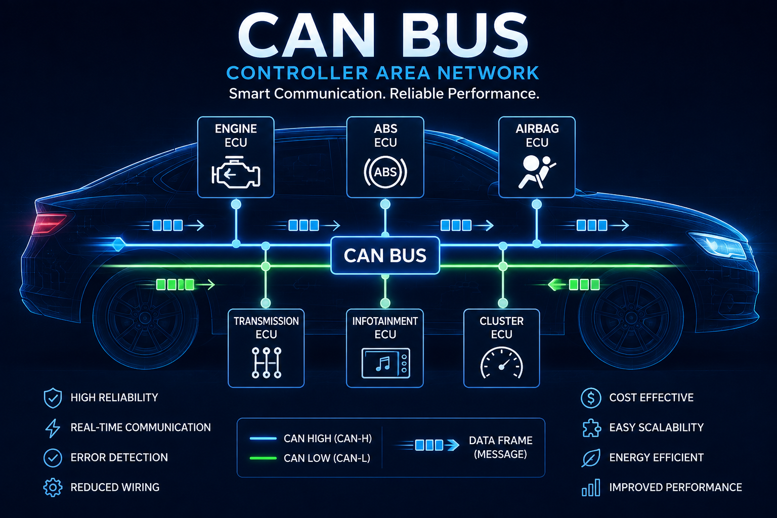
A single ECU is not very useful. The engine ECU needs wheel speed that the ABS module measures; the dashboard needs engine speed. Rather than running a wire for every signal, ECUs share a bus.
CAN is still the workhorse. It is a two-wire differential bus where every node hears every message, messages carry an identifier rather than a destination address, and the lowest identifier automatically wins when two nodes transmit at once. That arbitration is non-destructive — the winning message is not corrupted and does not need retransmitting.
For a typical powertrain network you might see engine speed broadcast every 10 ms, wheel speeds every 20 ms, and diagnostic responses only when requested. Newer platforms add CAN FD for larger payloads and automotive Ethernet where cameras and sensor fusion need real bandwidth.
If you want the bus layer properly rather than as a summary, our CAN Protocol Masterclass covers arbitration, bit timing, error handling and DBC files in depth.
How ECU software is structured
Early ECUs were a single C program talking directly to registers. That does not scale across a supplier network, so the industry standardised on AUTOSAR, which splits ECU software into layers:
Application layer — the actual control logic, portable between hardware
Runtime Environment (RTE) — the glue that connects components
Basic Software (BSW) — drivers, communication stacks, diagnostics, OS
Microcontroller Abstraction Layer (MCAL) — the only part that knows the specific chip
The point is that a car maker can specify behaviour, a supplier can implement it, and swapping the microcontroller two years later ideally only changes the bottom layer. In practice it is messier than that, but the separation is real and it is what most job descriptions are asking about.
Problems engineers actually hit
Three failures come up constantly when people start working on ECUs.
Signal scaling errors. CAN signals are packed as raw integers with a scale factor and offset defined in a DBC file. Get the factor wrong and your engine speed reads 8000 rpm at idle.
/* Engine speed: 16-bit, factor 0.25, offset 0, unit rpm */
uint16_t raw = (uint16_t)((frame.data[1] << 8) | frame.data[0]);
float engine_speed_rpm = raw * 0.25f;   /* NOT raw directly */
Missing bus termination. CAN needs 120 Ω resistors at both physical ends of the bus and nowhere else. One missing terminator gives you reflections that look like random, intermittent, impossible-to-reproduce errors.
Blocking in an interrupt. A delay loop or a bus wait inside an interrupt handler will blow your timing budget and eventually trip the watchdog. Interrupts set flags; the main loop does the work.
Where to go next
If you are learning this material in order, the sequence that works is: understand the ECU as a control loop, then the network it lives on, then the diagnostic protocol layered on top, then the software architecture that organises it all.
Start with the bus. Almost every automotive software role assumes CAN fluency, and it is the layer you will spend the most time debugging.